
Why Cam and Crank Signal Analysis Is the First Step in Timing-Related Diagnosis
P0016, P0341, variable valve timing faults, and phantom misfires can all trace back to the signals between the crankshaft and camshaft sensors. Here is how Shaw’s reads them.
The crankshaft and camshaft sensors give the engine control unit its reference for timing — where each cylinder is in its firing sequence and when fuel and spark should be delivered. When these signals disagree, or when one is absent or intermittent, the faults that result can look like a misfire, a no-start, a VVT malfunction, or a timing chain stretch, depending on which sensor is affected and how badly.
What the sensors do
The crankshaft position sensor (CKP) reads a toothed reluctor ring on the crankshaft and tells the ECU the engine’s rotational position and speed. The camshaft position sensor (CMP) reads a similar ring on each camshaft and tells the ECU where the camshaft is relative to the crank. On engines with variable valve timing (VVT), the CMP signal is also used to control the timing of the intake and/or exhaust camshaft. If the CKP and CMP signals are not synchronised within the tolerance defined by the manufacturer, the ECU stores a correlation fault — commonly P0016 or P0017 on a petrol engine.
Why a fault code is not enough
A P0016 code (crankshaft/camshaft position correlation) does not tell you whether the fault is in the sensor, the reluctor ring, the timing chain, the VVT actuator, or the oil pressure to the VVT system. All of those can produce the same code. Replacing a sensor without investigating the signal is a guess that may not fix the problem.
Reading the signals directly
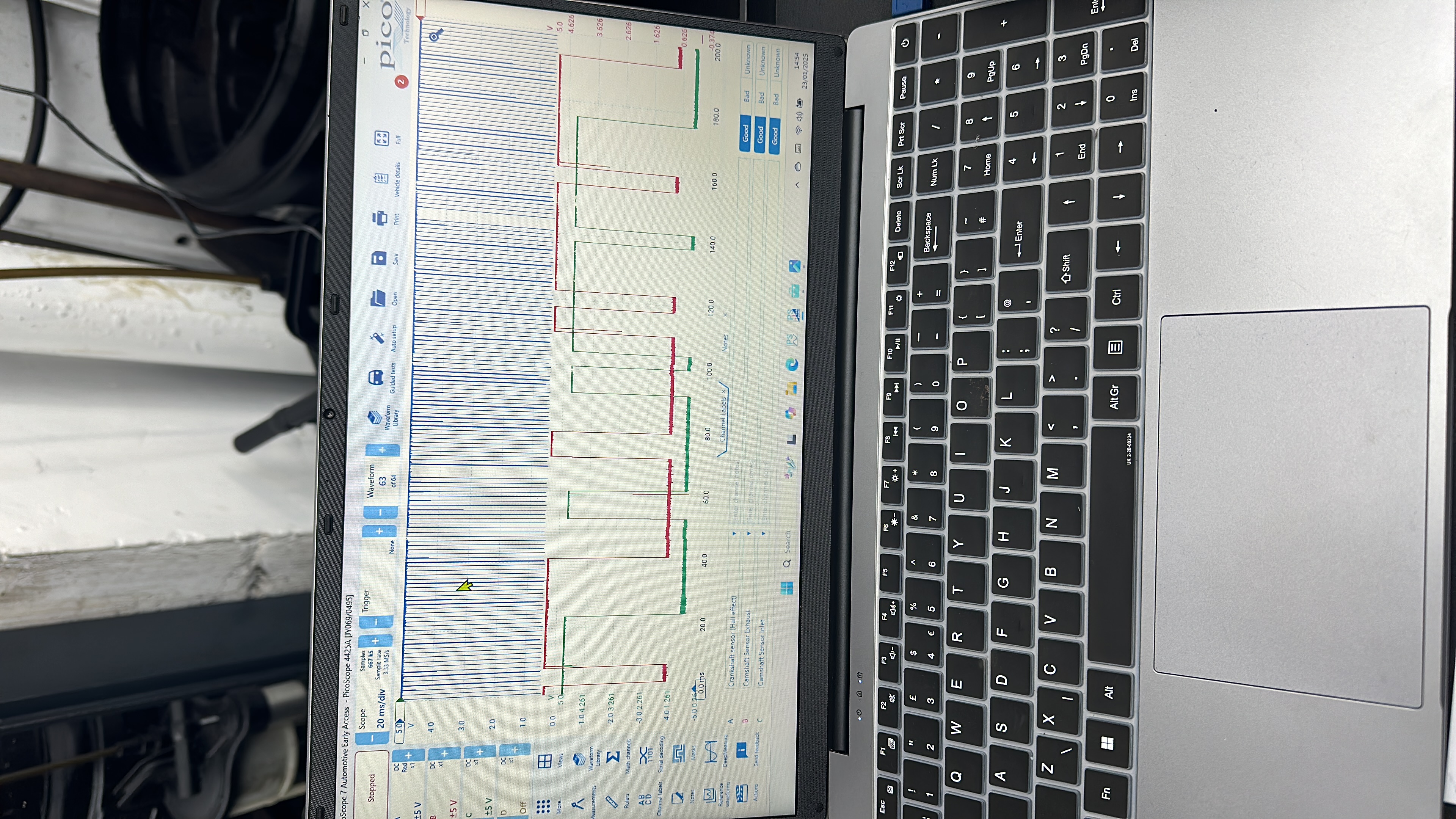
PicoScope 7 Automotive displaying live signals from three sensors simultaneously: the crankshaft (Hall effect), exhaust camshaft, and inlet camshaft. Each is showing a healthy, consistent digital square waveform with no signal dropouts or noise — confirming the sensors and their wiring are producing clean signals. When a fault is present, one channel will show missing pulses, noise, or a waveform that does not synchronise with the others.
At Shaw’s, we capture the CKP and CMP waveforms simultaneously on the PicoScope, comparing their patterns in real time. This shows us:
- Whether each sensor is producing a clean, consistent signal at the expected frequency
- Whether the timing relationship between the crank and cam signals is correct — or shifted, which would indicate chain stretch or a jumped tooth
- Whether a sensor signal is dropping out intermittently — which a scanner showing live data may average out and miss
- Whether a VVT actuator is responding correctly when the ECU commands a timing change
What a stretched timing chain looks like on the oscilloscope
A worn or stretched timing chain causes the camshaft to retard relative to the crankshaft — it arrives slightly late in each cycle. On the oscilloscope, the phase relationship between the CKP and CMP waveforms shows this retardation as an offset that exceeds the manufacturer’s tolerance. This is visible before any fault codes are stored, because the ECU tolerance threshold for storing a P0016 is wider than the range that causes noticeable performance problems.
Cam-crank diagnosis at Shaw’s
Timing-related fault codes and symptoms — particularly correlation codes, hesitation under VVT load, and cold-start rough running that clears when warm — are diagnosed at our Rhyl branch. The diagnostic assessment is £150.
Contact Shaw’s about timing system diagnosis →
We check it properly. We explain it properly. We do the job properly. You decide what gets done.
Shaw’s Service Station | Rhyl & Kinmel Bay | 01745 353481